Ventilator Installation
LUWA, VA Ventilator Series Operating & Install Instructions
Steel & Concrete- 1 bar (15 psi low blast) installations
Revised Dec. 6, 2018
Gas Filter (GF 40, 75, 150)
DO NOT OPEN THE GAS FILTER CAP ON THE GAS CANISTER UNTIL THERE IS A THREAT SITUATION. The filter cap must remain sealed until needed. If opened, the charcoal will pick up humidity and become saturated when exposed to the air. Do not try to open the gas filter canister. It has been sealed shut.
Use the bracket to secure the gas filter canister to the floor. If installing onto the wood floor of a steel shelter, you will need to provide your own bolts and anchors. Position the gas filter so that the center hole is closest to the air rate meter and throttle (#4).
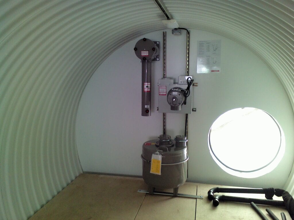
Air Ventilation, Motor & Gas filter (see ANDAIR page 1.14.017.1)
(a) Connections:
The air rate meter tube (#4) should be connected to the downspout of the pre-filter (#3). Apply some RTV silicone sealant to the gap between the metal connections leaving the bolts rather loose. After a day or two of curing, tighten the bolts snuggly, but not excessively.
The two-piece rubber hose connects the air rate meter tube (#4), to the air pump (#1). The hose is connected in the middle by a coupling clamp. The hose with the coupling clamp should be attached at the air rate meter tube (#4) side. The hose without a clamp should be connected to the air pump side of the ventilator (#1).
The coupling clamp connects the two hoses together when the gas filter is NOT in use. *It is recommended that you leave your coupling unconnected when the ventilator is not in use. This helps to prevent water from entering the motor in the unlikely event that the outside air vents become covered with water.
(b) Gas Filter:
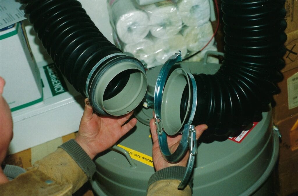
The gas filter (#6) should NOT BE OPENED until threat time. Do not even break the wire seal to the gas filter until needed for a threat of an NBC incident. If there is a threat, break the seal, unclamp the hose and open both openings to the gas filter. The hose with the coupling connects to the center opening (down arrow) of the gas filter. The hose without a coupling connects to the side opening of the gas filter (up arrow).
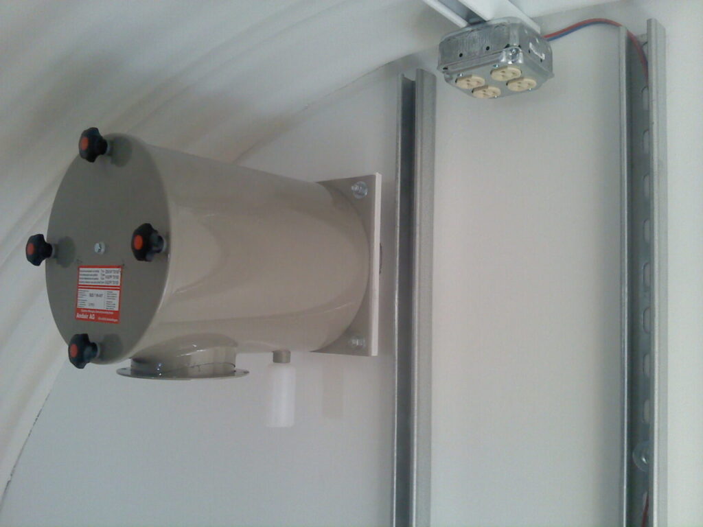
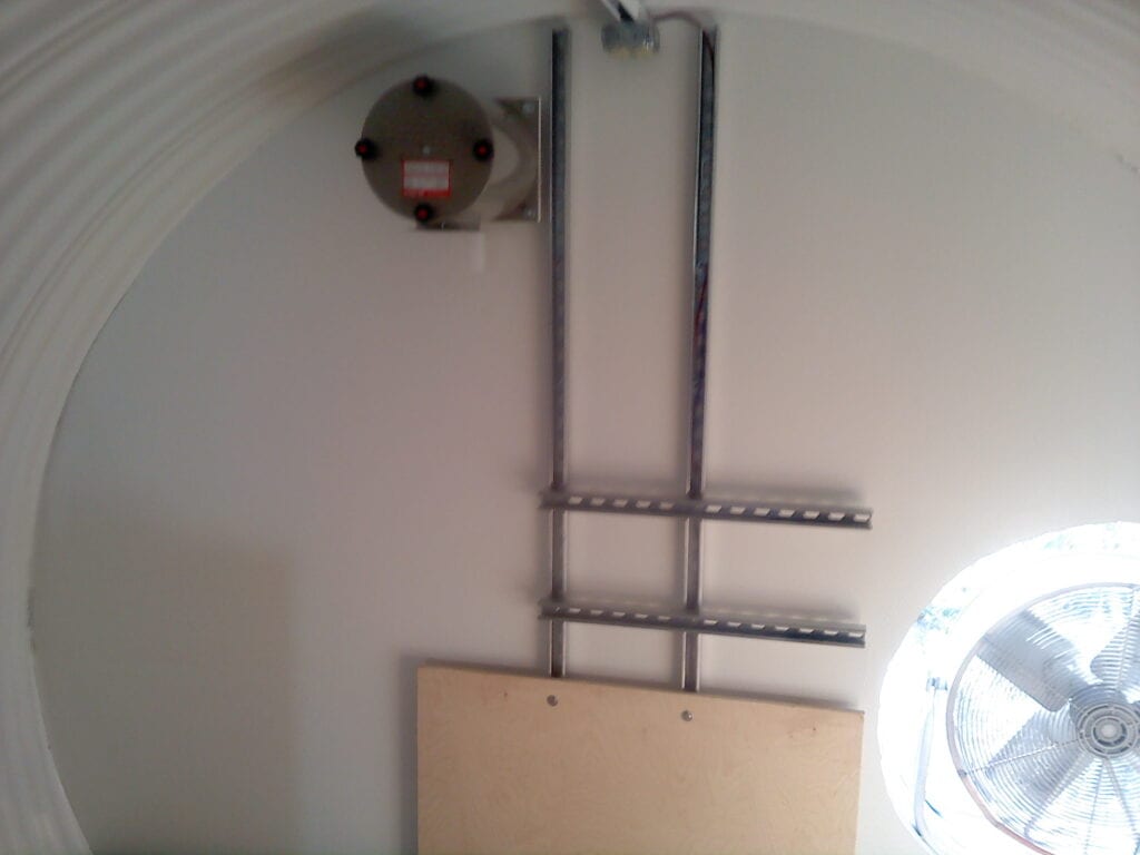
ESV/VF Blast Valve and Pre-filter canister (See ANDAIR page 1.14.019.4)
The ESV/VF intake valve consists of a blast valve, pre-filter canister (with filter material) and condensation collector bottle.
The existing filter material (#4) in the pre-filter canister has been treated for chemical/biological filtration. Do not remove it or replace it with other filtration material. It is a pre-filter only and does not stand alone as a filtration device. Replacement filter cartridges can be purchased. During peacetime, if your pre-filter becomes dirty, the entire pre-filter canister must be removed and replaced with another canister. After or during a chemical or biological attack, the pre-filter should not be removed or changed, as you risk contamination to yourself and your shelter. NBC replacement filters for the pre-filter are available for purchase.
Directions for pre-filter replacement:
Condensation from the outside air will collect in the collector (#5). Empty the collector when needed.
UV/ESV Exhaust Valves
The UV/ESV is the exhaust blast valve for your system. In order to circulate the air properly, it should be placed on the opposite wall from the ventilator. Place the arm so that it hangs in a vertical position on the bottom half of the valve.

Air Pipes
Ventilation pipes should be constructed from 5 or 6-inch diameter schedule 40 steel pipe. The pipe must enter the shelter wall in a horizontal configuration.
The intake pipe should enter the wall at about 72 inches from the shelter floor and should clear the ceiling by 10 to 12 inches. The exhaust pipe should be at the opposite wall of the shelter and can be placed at any convenient height.
The air pipe must protrude 2 to 3-inches into the inside wall for 3-bar concrete installations and all steel shelter installations (both 1 bar and 3 bar). The air pipes may be placed flush to the inside wall in concrete 1-bar installations.
The intake pipe can run horizontally, underground for up to 30 feet, before turning upward to reach above grade to the air source. It is recommended that the intake pipe have at least an 18-inch rise above ground and that it end in a “goose neck” configuration. This keeps debris from falling into the pipe. In areas of high blast potential, the air vent can be placed into a “rock crib” (as seen on the Utah Shelter Systems web page).
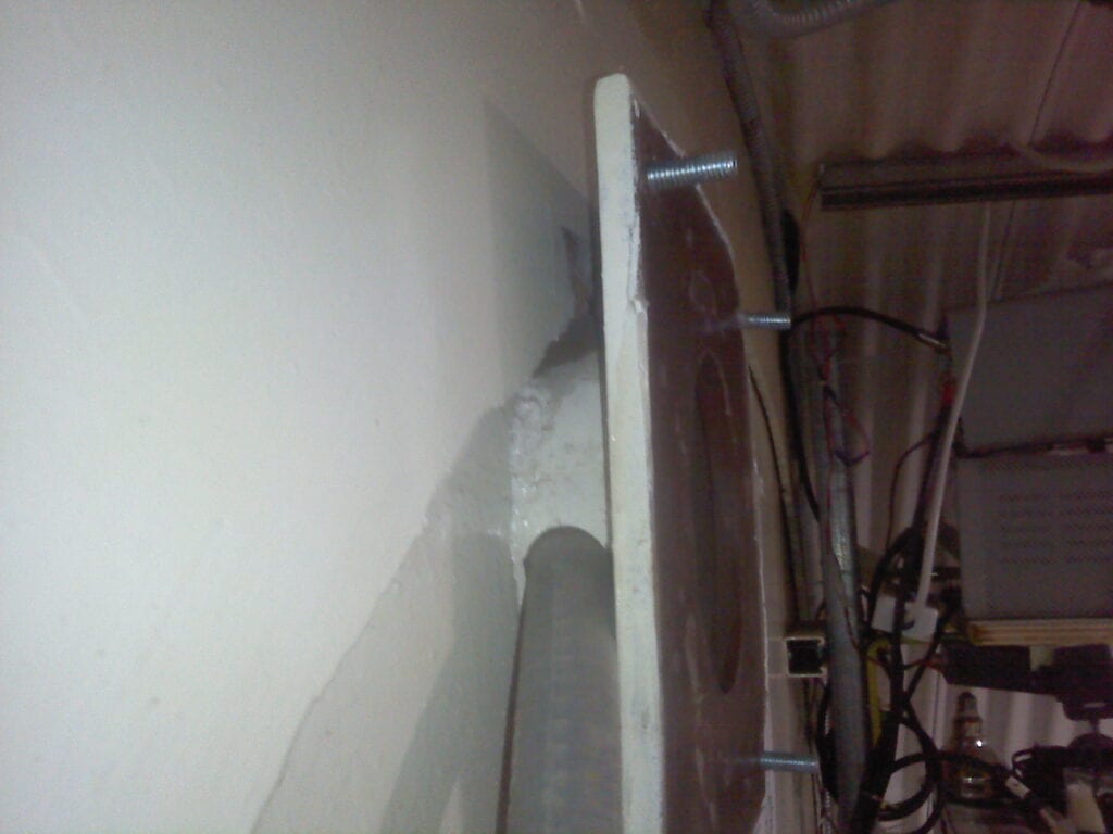
Ventilation Installation in Steel Shelters
Ventilation Installation in Concrete Shelters
FUNCTION
Check for proper function: Close your shelter doors. Turn the ventilator to the “on” position (or manually turn the ventilator with the handle). If your shelter is airtight, the UV/ESV should open slightly during ventilation. It will close when the ventilator is not functioning. If the UV/ESV does not open during ventilation, check the seals on your doors for leakage. The shelter must maintain a slightly positive pressure to ensure that no war gasses will enter the shelter during threat time. Run the ventilator for 15 minutes at least once a month.
Throttle Function:
Motor Operation: Turn the throttle to the off position. Turn the power switch to the ‘on’ position. Adjust the throttle to the blue mark for ventilation only. Adjust the throttle to the red mark for ventilation with gas filter.
Manual Operation: Turn the throttle to the full “on” position. Manually turn the crank handle until the air rate meter reads in the blue mark position for ventilation only, and in the red mark position for ventilation with gas filter.